Với hơn 10 năm kinh nghiệm về vận chuyển khí nén, Headpowder Sơn Đông cung cấp hệ thống, thiết bị và quạt gió toàn chuỗi, đảm nhận các dự án kỹ thuật bột trọn gói trên toàn quốc.
When designing a pneumatic conveying system for flake graphite, it is crucial to consider multiple factors to ensure efficiency, reliability, and cost-effectiveness. The process involves a systematic approach that integrates material properties, system components, and operational requirements. This guide from Shandong HeadPowder Engineering Co., Ltd. outlines key considerations and steps to develop an optimal system plan.
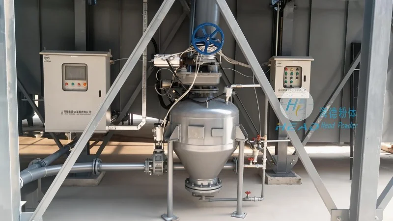
Understanding Flake Graphite Properties and Handling Requirements
Flake graphite, known for its excellent electrical conductivity and lubricity, presents unique handling characteristics. Its particle size, density, and flowability directly impact the choice of conveying method and equipment. For instance, the typical flake graphite particle size ranges from 0.1 to 5 mm, with a bulk density of approximately 1.5 to 2.2 g/cm³. These properties influence the selection of air velocity, pressure, and system configuration. A thorough analysis of these material attributes is essential to avoid system inefficiencies or equipment damage.
Key Components of a Pneumatic Conveying System
The core components of a pneumatic conveying system for flake graphite include the material feed hopper, air compressor, conveying line, and discharge receiver. The feed hopper must be designed to handle the bulk material and ensure consistent feeding into the system. It often incorporates a feeder mechanism, such as a rotary valve or screw feeder, to regulate the material flow rate. The air compressor provides the necessary pressure and volume of air to transport the graphite particles through the pipeline. The conveying line, typically made of stainless steel or other corrosion-resistant materials, must withstand the abrasive nature of flake graphite and maintain air-tight integrity. The discharge receiver collects the material at the end of the conveying line and may include a silo or storage tank for further processing.
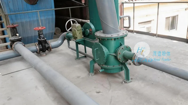
System Design Considerations: Pressure and Air Velocity
Two critical parameters in pneumatic conveying are system pressure and air velocity. The pressure level determines the conveying capacity and distance, while air velocity affects the risk of particle degradation or system blockage. For flake graphite, a low to medium pressure system (e.g., 0.5 to 2 bar) is commonly used, as higher pressures may cause particle breakage or excessive energy consumption. The air velocity should be maintained above the minimum fluidization velocity to prevent material settling but below the maximum velocity to avoid excessive wear on the pipeline and equipment. Proper calculation of these parameters ensures optimal system performance and longevity.
Material Feed and Conditioning Equipment
The material feed and conditioning equipment play a vital role in maintaining system efficiency. The feed hopper may include a pre-screening or de-dusting system to remove oversized particles or contaminants that could damage the conveying line or affect material quality. Additionally, a material conditioning device, such as a vibratory feeder or agitator, can help improve material flowability, especially for cohesive or sticky graphite. These components ensure a consistent and controlled feed rate, preventing surges or blockages that could disrupt the conveying process.
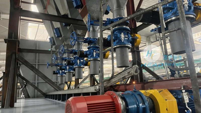
System Integration and Control
Integrating the pneumatic conveying system with other processing equipment, such as grinding or packaging units, requires careful planning. The system should be designed to interface seamlessly with downstream processes, ensuring smooth material transfer and minimizing downtime. Control systems, including pressure sensors, flow meters, and programmable logic controllers (PLCs), are essential for monitoring and regulating system performance. These controls allow operators to adjust parameters in real-time, respond to changes in material feed or demand, and maintain optimal operating conditions.
Installation and Maintenance Recommendations
Proper installation and regular maintenance are critical to the long-term performance of the flake graphite pneumatic conveying system. The conveying line should be installed with appropriate slopes to facilitate material flow and prevent settling. Regular inspection of components, such as the air compressor, feed hopper, and conveying line, is necessary to identify and address potential issues before they escalate. Maintenance tasks may include cleaning the conveying line, replacing worn parts, and checking for air leaks. By adhering to a regular maintenance schedule, the system can operate efficiently and reliably, reducing downtime and maintenance costs.
Conclusion: Developing an Optimal System Plan
Designing a reasonable flake graphite pneumatic conveying system involves a comprehensive approach that considers material properties, system components, operational parameters, and maintenance requirements. By following the guidelines outlined above and leveraging the expertise of companies like Shandong HeadPowder Engineering Co., Ltd., businesses can develop a system that meets their specific needs, enhances productivity, and ensures long-term reliability. The key is to balance efficiency, cost, and durability, resulting in a well-designed and effective pneumatic conveying solution for flake graphite handling.

 Shandong Headpowder Engineering Co., Ltd.
 156-6277-7102(Quản lý Trương)
  0531-83386006
  Thành phố Tế Nam, Tỉnh Sơn Đông, Trung Quốc
Điện thoại
WeChatTư vấn
Lên đầu